|
 Well Engineering
applications present unique demands for their user interface. A wide
variety of different technical applications can be used to support well
design and subsequent operations while drilling the well. Rig costs
for an offshore well can exceed $6K per hour ($100/minute), so
applications will only be used for operations support if they provide high
value and have a very low burden on the user. Well Engineering
applications present unique demands for their user interface. A wide
variety of different technical applications can be used to support well
design and subsequent operations while drilling the well. Rig costs
for an offshore well can exceed $6K per hour ($100/minute), so
applications will only be used for operations support if they provide high
value and have a very low burden on the user.
In addition, the market for well engineering applications is relatively
small (as is true with most vertical industry applications). The
increased user expectations for graphical user interfaces have made it
difficult for niche technical application vendors. Oil companies
have also had a more difficult time leveraging unique technology as
software products. The well engineering application framework was
developed to address these needs.
This topic presents the user objectives for the well engineering
application framework
along with screen shots to illustrate the system. The
software
architecture objectives are also discussed.
User Objectives
Drilling Engineers View - Each technical application has its own
requirements for well data, and the engineering developer designs the
input based on the needs of the calculations. Thus, pipe input is
usually inside and outside diameters; liners are combined with the prior
casing; well path data may require hole angle at different depths.
The drilling engineer identifies tubing and casing by OD and actual
weight; drill pipe by OD and nominal weight; and drill collars by OD and
ID.
 The
application framework requests input data using a drilling engineers view
of the data, and then translates the data as required for the engineering
application. In some cases, this is as simple as using a catalog for
pipe sizes to provide additional data. A more complex example is
allowing entry of casing scheme for the complete well, and then deriving
the current well geometry at any particular current depth. The
application framework requests input data using a drilling engineers view
of the data, and then translates the data as required for the engineering
application. In some cases, this is as simple as using a catalog for
pipe sizes to provide additional data. A more complex example is
allowing entry of casing scheme for the complete well, and then deriving
the current well geometry at any particular current depth.
Graphic Feedback for Input -
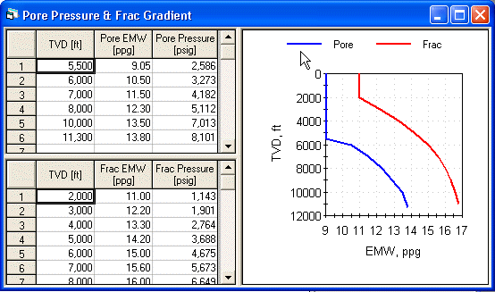
Graphic views are shown beside the data entry. These provide visual
feedback to ensure correct input. The example below shows a plot of
pore pressure and fracture gradient. The plot is updated with data
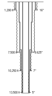
entry changes. The well sketch is also a valuable tool for graphic
feedback of well geometry.

Result Centric -
Calculated results presented in graph format are the key deliverables of
the applications. The toolbar shown below has three buttons on the
right for each of the result presentations. Results can be easily
accessed by clicking the button. Calculations are automatically
launched if needed.

Results are also available in tabular form. In
some cases, result forms are interactive and allow multiple views.
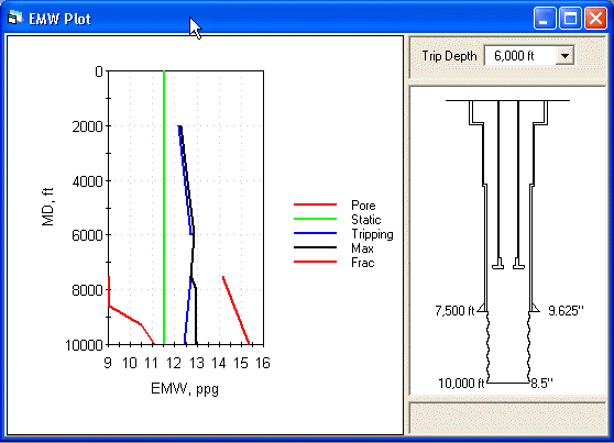
The example below shows pressure increase from static due to a pipe trip
with the drill bit at 6,000 ft. The well sketch helps to identify
any trends that may be due to well geometry.

World-wide Use - The engineering applications
are used around the world, and the units for input and output vary in
different locations. Wedelich Consulting developed the
UnitControls set of custom controls to facilitate data entry in
different unit systems. The controls include a text box, combo box
(where the selection pick list values are converted), and a grid (where
each column contains data of a different type). UnitControls
handles all of the required conversion logic, allowing the application to
work seamlessly with a consistent set of internal units.
UnitControls also provides the ability to create a custom set of units
for a particular location (the initial system includes English, Metric,
and Mixed unit sets), and UnitControls provides a unit calculator
for ad-hoc entry of values in any valid unit.
Catalogs to Reduce Entry - The application
framework includes a separate database that contains catalogs of the
different components used within the well. Example catalogs include
casing, drill pipe, HWDP, drill collars, and other BHA components.
Catalogs can also be used for input like rock properties. A standard
catalog database is available with the application, and a Catalog
Manager program is available to create user catalogs. User
catalogs can be used to either add new components, or to restrict the
components to those used in a particular area. The catalog system
significantly reduces user input and input errors.
Software Architecture Objectives
The primary architecture objective is easy addition
of new applications. This requires an
object oriented design
that allows common code to work with collections of data objects (pore
pressure, drill string, etc.), input forms, and result presentation
forms. Visual SourceSafe is used extensively to share
common code between applications. ActiveX component
libraries are used to share abstract interfaces and lower level common
objects. With the framework, a user interface for a new
application can be developed in weeks, instead of months.
Microsoft Access is used as the repository for
well and case data, including case results. MS Access is
also used for the catalog manager. This open format allows for
other uses of the well data - it also enables features like Copy Form,
where input data for a given form can be easily copied from some other
well or case. Tools were developed to upgrade a user database for
a new release of the applications.
The framework also includes a
concurrency broker ActiveX application that consolidates all
access to the database, prevents multiple applications from modifying
the same data, and provides notification when one application has
changed data.
The initial release of the well engineering framework
included 3 applications. Over a period of four years, additional
applications were added in several releases. The development
varied from two to five developers depending on the work load.
Seventeen different applications were developed over this period.
The applications have been very well received by the user community.
| 